Many people may not know how to use the placement machine, explain the principle of the placement machine, and safe operation. XLIN Industry has been deeply involved in the placement machine industry for 15 years. Today, I will share with you the working principle and safe operation process of the placement machine .
Placement machine: also known as “mounting machine” and “Surface Mount System”, in the production line, it is configured after the dispensing machine or screen printing machine, and the surface mount system is mounted by moving the mounting head. A device that accurately places components on PCB pads. The placement machine is a combination of machine, electricity, light and computer control technology. Through suction, displacement, positioning, placement and other functions, SMC/SMD components can be quickly and accurately attached to the designated pad position of the PCB without damaging the components and printed circuit board.
There are three centering methods for mounting components on the placement machine: mechanical centering, laser centering and visual centering. The placement machine consists of a frame, an x-y motion mechanism (ball screw, linear guide, drive motor), a placement head, a component feeder, a PCB carrying mechanism, a device alignment detection device, and a computer control system. The movement of the whole machine is mainly realized by the x-y movement mechanism, the power is transmitted by the ball screw, and the directional movement is realized by the rolling linear guide rail. This transmission form not only has small movement resistance, compact structure, but also high transmission efficiency.
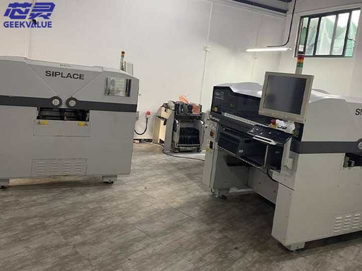
1. There are two types of placement machines: manual and fully automatic.
2. Principle: The arch-type component feeder and the substrate (PCB) are fixed, and the placement head (installed with multiple vacuum suction nozzles) moves back and forth between the feeder and the substrate to remove the components from the feeder. Adjust the position and direction, and then stick it on the substrate.
3. Because the patch head is installed on the X/Y coordinate moving beam of the arch type, so it is named.
4. The adjustment method of the position and direction of the components of the arch type mounter: 1), adjust the position by mechanical centering, and adjust the direction by rotating the suction nozzle. The accuracy that this method can achieve is limited, and the later models are no longer used.
5. Laser recognition, X/Y coordinate system adjustment position, suction nozzle rotation adjustment direction, this method can realize the identification during the flight, but it cannot be used for the ball grid display component BGA.
6. Camera recognition, X/Y coordinate system adjustment position, suction nozzle rotation adjustment direction, generally the camera is fixed, and the placement head flies across the camera for imaging recognition, which takes a little longer than laser recognition, but it can recognize any component, and there are also implementations The camera recognition system for recognition during flight has other sacrifices in terms of mechanical structure.
7. In this form, due to the long distance of the patch head moving back and forth, the speed is limited.
8. Generally, multiple vacuum suction nozzles are used to pick up materials at the same time (up to ten) and a double-beam system is used to increase the speed, that is, the placement head on one beam is picking up materials, while the placement head on the other beam is sticking Component placement is almost twice as fast as a single-beam system.
9. However, in practical applications, it is difficult to achieve the condition of taking materials at the same time, and different types of components need to be replaced with different vacuum suction nozzles, and there is a time delay in changing the suction nozzles.
10. The turret-type component feeder is placed on a single-coordinate moving material cart, the substrate (PCB) is placed on a worktable that moves in an X/Y coordinate system, and the placement head is installed on a turret. When working, the material The car moves the component feeder to the pick-up position, the vacuum suction nozzle on the patch head picks up the components at the pick-up position, and rotates to the pick-up position through the turret (180 degrees from the pick-up position). Adjust the position and direction of the components, and place the components on the substrate.
11. Adjustment method for component position and direction: camera recognition, X/Y coordinate system position adjustment, suction nozzle self-rotation adjustment direction, fixed camera, placement head flying over the camera for imaging recognition.
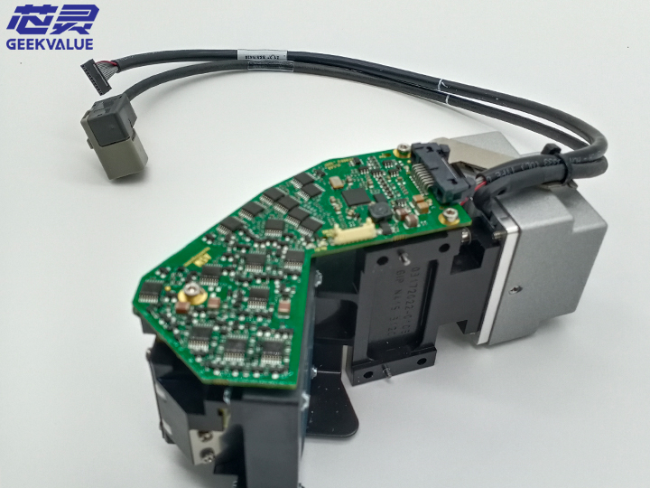
In addition, the placement machine marks important parts such as mounting shafts, moving/stationary lenses, nozzle holders and feeders. Machine vision can automatically calculate the coordinates of these marking center systems, establish the conversion relationship between the coordinate system of the placement machine and the coordinate system of the PCB and the mounted components, and calculate the precise coordinates of the placement machine. The placement head grabs the suction nozzle, and sucks the components to the corresponding position according to the package type, component number and other parameters of the imported placement components; the static lens detects, recognizes and centers the suction components according to the visual processing program; and passes through the mounting head after completion Mount the components on the PCB at predetermined positions. A series of actions such as component identification, alignment, detection, and installation are all automatically completed by the control system after the industrial computer obtains relevant data according to corresponding instructions.
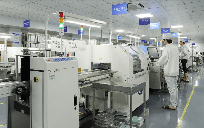
The placement machine is a device used for high-speed and high-precision placement of components, and it is the most critical and complex equipment in the entire SMT production. Mounter is a chip mounting equipment used in SMT production. The placement machine is to accurately place the placement machine in the corresponding position, and then glue it with pre-coated red glue and solder paste, and then fix the placement machine on the PCB through a reflow oven.
The safe operation of the placement machine should follow the following basic safety rules and procedures:
1. The power should be turned off when checking the machine, replacing parts or repairing and internal adjustment (the maintenance of the machine must be carried out with the emergency button pressed or the power cut off.
2. When “reading coordinates” and adjusting the machine, make sure the YPU (programming unit) is in your hand so that you can stop the machine at any time.
3. Ensure that the “interlock” safety equipment remains effective to shut down at any time, and the safety inspection of the machine cannot be skipped or shortened, otherwise it is easy to cause personal or machine safety accidents.
4. During production, only one operator is allowed to operate one machine.
5. During operation, make sure that all parts of the body, such as hands and head, are out of the moving range of the machine.
6. The machine must be properly grounded (truly grounded, not connected to the neutral wire).
7. Do not use the machine in a gas or extremely dirty environment.
Post time: Dec-17-2022